Research Report of 360VO Visual Odometry Using A Single 360 Camera
Research Report of 360VO: Visual Odometry Using A Single 360 Camera
Abstract—This article is a review and evaluation of the paper 360VO: Visual Odometry Using A Single 360 Camera in the 2022 IEEE International Conference on Robotics and Automation (ICRA). Starts from this article and summarizes the method of it and then presents the related works. Then, some improvement directions are proposed for this article. Finally, the commercial value and social value of the visual slam field are discussed. After decades of development in the field of visual slam, good localization and mapping effects have been achieved. This article proposes a slam framework based on 360 cameras and combines direct methods to complete localization and mapping tasks. Experiments show that the method proposed in this paper has good robustness and accuracy.
EXECUTIVE SUMMARY
This article is a summary and review of the paper 360VO: Visual Odometry Using A Single 360 Camera published in the 2022 IEEE International Conference on Robotics and Automation (ICRA). This paper uses a 360° omnidirectional camera to complete the simultaneous localization and mapping task (SLAM). simulation experiment and the real indoor and outdoor mapping experiments using a handheld 360° camera demonstrate that the method achieves good results. A 360 camera is a special kind of camera that can capture 360° horizontal and 180° vertical information at once.
360° camera can be achieved using only 2 fisheye cameras placed back-to-back. This significantly reduces costs, such these commercial products are becoming more popular and accessible, such as insta 360, go pro, etc. To utilize 360° cameras for localization and mapping, this paper proposes slam method based on direct method. Direct methods estimate camera pose and depth features by minimizing the photometric error. Pinhole and various fisheye camera models are not suitable for describing projections from 360 cameras. This paper proposes an appropriate 360 camera model, which uses a spherical model for projection. Images using equidistant projection assume that the 360 camera is an undistorted camera. The spherical camera model only needs two parameters, namely the width and height of the image, to complete the projection. The defined photometric error in DSO is expressed as the energy loss of the corresponding pattern. For the mapping, this paper models the inverse depth estimation of points with probability distributions. The depth range was initially assumed over a wide range. As new frames appear, it will continuously search for the best corresponding point to estimate depth more accurately. In order to speed up the search and guarantee the accuracy, the search process should follow the epipolar constraints. This paper searches for the minimum error on the epipolar line with a certain step to complete the depth estimation. To quantitatively evaluate the performance of this method, this paper proposes a synthetic dataset with dense features. The dataset contains 10 sequences whose features appear in different urban models. 360VO achieves a similar effect compared to the indirect method of Open-VSLAM. At the same time this article cuts the image and then runs orb-slam3. Apparently, methods using 360 cameras are generally more robust and accurate because there is more features in widefield camera than normal cameras. Then, physical experiments of indoor and outdoor mapping based on handheld 360 cameras have well demonstrated the effect of the algorithm.
BACKGROUND
The visual odometry (VO) or visual-inertial odometry (VIO) problem has been extensively studied in the past few decades. This problem mainly uses the information obtained from the image to complete the estimation of camera pose and the estimation of 3D landmarks in map. Visual SLAM platforms can be mainly divided into three categories according to different camera types: monocular cameras, stereo cameras and RGBD cameras. The monocular camera refers to a system that uses a single camera to complete mapping (such as Apple ARKit). stereo camera refers to a system that uses two cameras with known extrinsic parameters to complete the mapping (such as Leap Motion, ZED). Since the monocular camera loses the scale information in the process of pose estimation, it is necessary to introduce auxiliary method such as odometer to calculate the scale information. However, the scale information can be more easily recovered when the stereo cameras are used. Neither monocular nor binocular cameras can easily calculate depth information, and the use of RGBD cameras is a good solution to this problem. RGBD cameras usually use the time-of-flight method ToF (such as Microsoft Kinect-2), and the structured light method (such as Microsoft Kinect-1, Apple Prime Sense) to obtain depth information [1]. good positioning and mapping performance can also be obtained in areas such as dark light and weak textures. But its higher cost compared to cameras limits its widesp use.
MonoSLAM [2][3] is the pioneer work of visual slam systems. Produced by Andrew J Davison with support from the Engineering and Physical Sciences Research Council (EPSRC) Advanced Research Fellowship programme in the UK. MonoSLAM uses Extended Kalman Filter as the backend to track sparse feature points in the frontend. MonoSLAM is based on EKF, taking the current state of the camera and all landmark points as state quantities, and updating its mean and covariance.
In 2007, Klein et al. proposed PTAM (Parallel Tracking and Mapping) [6], which is also an important event in the development of visual SLAM, and the project was mainly funded by Oxford University. The significance of PTAM lies in the following two aspects:
- PTAM proposes and realizes the parallelization of the tracking and mapping process.
- PTAM is the first slam framework to use nonlinear optimization instead of traditional filter as backend.
- The system also introduces a keyframe mechanism to reduce computation and better optimize the map.
ORB-SLAM is a very famous successor of PTAM [7], This work was supported by the Direccion General de Investigaci ´ on of ´ Spain. It was proposed in 2015 and is one of the most well-established and easy-to-use systems in modern SLAM systems. Currently ORB-SLAM has been developed to ORB-SLAM3[8]. The advantages of the ORB-SLAM3 system can be mainly summarized as follows:
- Supports monocular, binocular and RGBD modes.
- The system mainly based on calculate FAST-ORB feature, including visual odometry and close-loop detection modules. Compared with feature points such as SIFT or SURF, ORB feature points have faster calculation speed and can realize real-time calculation. In addition, the feature descriptor of ORB can provide certain rotation and scaling invariance.
- The system introduces a loop closure detection system based on hierarchical clustering model DBoW2[5]. Compared with the traditional SLAM system based on extended Kalman filter, this system can better solve the problem of cumulative error. At the same time, it can be quickly retrieved after being lost.
- The system uses multiple threads to synchronously complete the tasks of tracking, local optimization and global optimization, making the operation more efficient.
The main system components of orb-slam are shown in Figure 1
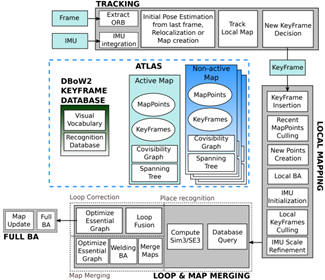
Figure 1 Main system components of ORB-SLAM3
Large Scale Direct monocular SLAM is a SLAM work proposed by J. Engle et al. in 2014 [9][10], sponsored by the Technical University of Munich. Unlike ORB-SLAM, which uses feature points to extract image features, LSD-SLAM uses a direct method to complete feature extraction. The core contribution of LSD-SLAM is the application of direct methods to semi-dense monocular SLAM. Not only does it not need to compute feature points, it also builds semi-dense maps. Compared with the feature point method, the direct method can be used to complete the mapping in the missing feature point area, but it is prone to loss problems when the camera moves too fast. Furthermore, since loop closure detection usually relies on the clustering of feature points[5], LSD-SLAM still needs to compute feature points.
Semi-direct Visual Odoemtry (SVO) [11]. It is a semi-direct method based visual odometry proposed by Forster et al. The framework mixes feature points with direct methods. SVO tracks some keypoints and then performs block matching to estimate camera motion. Since it uses the sparse direct method, it neither has to work hard to compute descriptors nor deal with as much information as dense and semi-dense, so it can achieve real-time performance even on low-end computing platforms. Some commonly used SLAM systems can be summarized in Table 1.
The core of visual SLAM is to estimate the pose and position of the camera and landmarks, and the key to the estimation is to extract the information in the image. A larger field of view can provide cameras with more features and a larger common field of view between cameras. Thereby reducing the occurrence of dropped frames, and can better complete the mapping task[12]. But the wide-angle camera has more serious distortion problems, and the ordinary pinhole camera model is not enough to directly express the wide-angle camera. Therefore, many scholars have done extensive research in this area. Caruso[13], and Matsuki [14] et al. established SLAM systems using omnidirectional cameras in LSD-SLAM and DSO, respectively, by introducing a generic camera model. Furthermore, the Kannala Brandt camera model [15] is used in Campos [16] et al. to support fisheye cameras as input in ORB-SLAM3.
Some scholars have also devoted themselves to using more cameras to complete feature extraction with larger field of view. MULTICOL-SLAM [17] proposed a fast and applicable SLAM system based on multiple cameras. ROVO [18] is also a similar multi-camera SLAM system. The system uses a hybrid projection model that uses 4 cameras to cover a 360° field of view to detect the environment. However, the above-mentioned system based on the multi-camera model requires multiple cameras, thereby increasing the cost of use, and more cameras significantly increase the complexity of calibration. Using the reflection of the lens can also increase the viewing angle of the camera. X. Long [4] and others from the Institute of Automation, Chinese Academy of Sciences installed a high-speed mirror in front of the camera and assisted the high-speed camera. In the case of using only a single ordinary pinhole camera, a wide-angle camera is virtualized to complete multi-target extraction. This method can ensure local high resolution while obtaining a large field of view, but its complex mechanical structure limits the use of the scene. The above-mentioned methods for increasing the field of view are all complicated. An easy way to do this is to use two wide-angle cameras arranged back-to-back to form a 360° wide-angle system. The OpenVSLAM [19] system can support such camera input and use the feature point-based slam algorithm to complete the mapping task. This paper proposes the 360VO framework, uses a photometric error-based approach to recover camera pose, and introduces epipolar constraints to recover the coordinates of landmark points.
TABLE 1 COMMON USED VISUAL SLAM FRAMEWORK
| framework | sensor type | sponsor webpage |
|---|---|---|
| MonoSLAM | monocamera | University of Oxford https://github.com/hanmekim/SceneLib2 |
| PTAM | monocamera | University of Oxford http://www.robots.ox.ac.uk/~gk/PTAM/ |
| ORB-SLAM | mainly monocamera | University of Zaragoza http://webdiis.unizar.es/~raulmur/orbslam/ |
| LSD-SLAM | mainly monocamera | Technical University of Munich http://vision.in.tum.de/research/vslam/lsdslam |
| SVO | monocamera | University of Zurich https://github.com/uzh-rpg/rpg_svo |
| DTAM | RGB-D | Imperial College London https://github.com/anuranbaka/OpenDTAM |
| DVO | RGB-D | Technical University of Munich https://github.com/tum-vision/dvo_slam |
| DSO | monocamera | Technical University of Munich https://github.com/JakobEngel/dso |
| RTAB-MAP | stereo cameras/RGB-D | University of Sherbrooke https://github.com/introlab/rtabmap |
| VINS-Fusion | monocamera/stereo cameras | HKUST https://github.com/HKUST-Aerial-Robotics/VINS-Fusion |
CONTRIBUTION
The main contributions of this article are as follows:
- A projection model based on a 360° camera is proposed.
- An epipolar constraint relation suitable for 360 cameras is proposed, and an error search strategy based on epipolar is designed.
- A back-end error optimization model based on local windows is designed.
360 camera model
The camera model is used to express the relationship between the real world coordinate system $\Omega$ and the camera image coordinate system $\Psi$. Let $u=\left[u,v\right]^T \in \Psi$ represent the coordinate point in the image coordinate system, and let $X_c=\left[X_c,Y_c,Z_c\right]^T\in\Omega$ represent points in the camera coordinate system. The camera model in this article refers to the need to find a mapping relationship $\pi:\ \Omega\rightarrow\Psi$ to express the relationship between 3D points and 2D points. Conversely, $\pi^{-1}:\Psi\rightarrow\Omega$ can be used to express the mapping relationship between 2D points and 3D points. Generally speaking, the ordinary camera based on the pinhole imaging model can be expressed by the following formula.
$$
s\left[ \begin{matrix} u \ v \ 1 \ \end{matrix}\right ]=\left[ \begin{matrix} f_x & 0 & c_x\ 0 & f_y & c_y \ 0 & 0 & 1 \ \end{matrix} \right]\left[ \begin{matrix} X_c \ Y_c \ Z_c \ \end{matrix} \right ]
$$

Figure 2 Coordinate systems used in 360VO. It takes advantage of a spherical model to represent camera projection, and the 2D image is in equirectangular projection.
However, this camera model cannot express a camera model with a field of view exceeding 180°. Therefore, a spherical projection model suitable for 360 cameras is proposed. As shown in Figure 2, the projection model projects the points in the world coordinates onto the unit sphere to complete the mapping between 3D and 2D points. The projection model can be expressed by the following formula:
$$
\pi\left(X_c\right)=\left[\begin{matrix}u\v\\end{matrix}\right]=K\left[\begin{matrix}lon\lat\\end{matrix}\right]=K\left[\begin{matrix}arctan\left(X_c/Z_c\right)\-arcsin\left(dY_c\right)\\end{matrix}\right]
$$
Where $d=1/\sqrt{X_c^2+Y_c^2+Z_c^2}$ represents the reciprocal of the distance from the 3D point to the unit sphere. lon and lat represent the latitude and longitude on the sphere. $-\pi < lon < \pi$ and $-\pi/2 < lat < \pi/2$. The last K represents the camera intrinsic parameter.
$$
\mathbf{K}=\left[\begin{matrix}f_x&0&c_x\0&f_y&c_y\\end{matrix}\right]=\left[\begin{matrix}W/2\pi&0&W/2\0&-H/\pi&H/2\\end{matrix}\right]
$$
Camera pose and landmark estimation
get camera pose
This article uses the direct method to complete the estimate of camera pose and landmark point coordinates. The direct method usually uses the method of minimizing the energy function to complete the optimal pose estimation of the camera. the energy function of a pixel $p \in\ \Psi$ in the host frame $i$ regrading to a co-visible target frame $j$ is
$$
\begin{aligned}
& E_{\mathbf{p}}^{i j}=\sum_{\mathbf{u} \in N_{\mathrm{p}}}|r|=\sum_{\mathbf{u} \in N_{\mathbf{p}}} w_{\mathbf{u}}\left|\left(I_j\left[\mathbf{u}^{\prime}\right]-b_j\right)-\frac{t_j e^{a_j}}{t_i e^{e_i}}\left(I_i[\mathbf{u}]-b_i\right)\right| \
& \mathbf{u}^{\prime}=\pi\left(\mathbf{R}{j i} \pi^{-1}\left(\mathbf{u}, \hat{d}^{\mathbf{p}}\right)+\mathbf{t}{j i}\right) \
& {\left[\begin{array}{cc}
\mathbf{R}{i j} & \mathbf{t}{i j} \
0 & 1
\end{array}\right]=\mathbf{T}_{i j}=\mathbf{T}_j \mathbf{T}i^{-1}}
\end{aligned}
$$
In this paper, the weighted sum of squared differences (SSD) algorithm is used to calculate the matching error, specifically, there are 8 pixels between each matching block, i.e., 8 pixels share the same depth. $T_i^{-1}$ and $T_j^{-1}$ are the representations of the $i-th$ frame and the $j-th$ frame in the world coordinate system. $u^$ prime and $u$ represent the correspond pixels to be calculated in the $j$ frame and the $i$ frame, respectively. $t{ji}$ represents the exposure time between frame $i$ and frame $j$. Finally combining the pixels of all neighborhood frames, the final energy function can be expressed as:
$$
\boldsymbol{E}=\sum_{i \in F}\sum_{\boldsymbol{p}\in P_i}\sum_{j \in obs(\boldsymbol{P})}{E_{\boldsymbol{P}}^{ij}}
$$
where $F$ represents frames contained in local optimization window, $P_i$ represents a set of selected points in the frame $i$ and are randomly sampled from directional points with local gradients above a certain threshold, and $obs\left(p\right)$ represents the frames that can observe point $p$. The optimization method of bundle adjustment is used.
Calculate landmark pose
Different from methods such as ORB-SLAM that use feature points, the direct method lacks the direct correspondence between two pixels. therefore, it is difficult to directly determine the depth of landmark points. Similar to other systems using the direct method [20][21][22][23], this paper also uses a preset depth range and an epipolar constraint to find the optimal pixel disparity and generate a semi-dense map. However, since this paper uses a camera projection model different from the pinhole model, it is necessary to derive a new epipolar constraint relationship on the spherical surface, as shown in Figure 3.

Figure 3 Epipolar constraints. When tracking succeeds, it needs to create new activated points and refine their inverse depth via triangulation. High corresponding points of host frame $c_i$ lie in the epipolar curve instead of line in the target frame $c_j$
Let the epipolar plane be $\rho$ and the unit sphere plane be $S$, then the constraints in the camera coordinate system $\Omega$ can be expressed as follows:
$$
\left{\begin{array}{l}
\rho: a X+b Y+c Z+d=0 \
S: \quad X^2+Y^2+Z^2=1
\end{array}\right.
$$
Combined with the 360 camera projection model derived above, the following constraints on the epipolar curve in the pixel coordinate system can be obtained:
$$
\mathbf{u}(\alpha)=\pi(\alpha \mathbf{P}_0^{\prime}+(1-\alpha) \mathbf{P}_\infty^{\prime} ), \alpha \in[0,1]
$$
$$
\mathbf{P}0^{\prime}=\pi_s\left(\mathbf{R}{j i} \pi^{-1}\left(\mathbf{p}, \hat{d}{\text {min }}\right)+\mathbf{t}{j i}\right)
$$
$$
\mathbf{P}\infty^\prime=\pi_s(\mathbf{R}{ji} \pi^{-1}(\mathbf{p}, \hat{d}{\max })+\mathbf{t}{ji})
$$
Where $P_0^\prime P_\infty^\prime$ represents the projection point of point $p$ in frame $i$ at the maximum disparity and the minimum disparity in frame $j$.
local optimization
In order to enhance robustness and reduce a certain amount of computation, this article uses bundle adjustment to optimize local frame and landmark coordinates. In this paper, the local frame selection is 7 adjacent keyframes and 2500 landmark points.
keyframe selection
The quality of key frame selection determines the quality of the map. In this article, the relative pose between the current frame and the previous key frame is calculated, and when the relative distance reaches a certain threshold, the frame is recorded as a new key frame. At the same time, since this article is based on the direct method, since the direct method has the assumption of illumination invariance, it is necessary to generate new key frames when the ambient light changes greatly.
Optimization
This article uses the Gauss-Newton method to complete the optimization of camera intrinsic parameters, extrinsic parameters, and optical flow parameters. Here, the disturbance derivation method on the SE3 manifold is used to complete the derivation. Its Jacobian matrix can be expressed as follows:
$$
\mathbf{J}_{\mathbf{M}=\left(\mathbf{T}_i,\mathbf{T}_j,\hat{d},\mathbf{K},a_i,b_i,a_j,b_j\right)}=\left[\frac{\partial r\left(\left(\delta+x\right)\boxplus\zeta_0\right)}{\partial\delta}\right]
$$
where $\zeta_0\in SE\left(3\right)$ and $\boxplus$ denotes the operation: $se{\left(3\right)}\times SE\left(3\right)\rightarrow SE\left(3\right)$.
Evaluation
This article innovatively proposes a SLAM framework based on 360 cameras. This paper proposes a projection model for the 360 camera and derives the epipolar constraints of the sphere from this model. In addition, this paper combines the direct method to complete the localization and mapping tasks. But I think this article still has some things worth improving.
- Wide-angle cameras generally have large distortions, but this article does not consider the distortion, whether the quality of the mapping will be improved after the distortion correction model is introduced.
- This article uses a spherical projection model to model a 360 camera, but the physical model of the camera is composed of two 180 wide-angle cameras arranged back-to-back. The optical centers of the two cameras are not completely coincident, and if the two wide-angle cameras do not have the same internal parameter matrix K due to the existence of manufacturing tolerances, whether the projection model proposed in this paper can correctly handle this situation.
- This article uses the bundle adjustment method to obtain the intrinsic and extrinsic parameters of the camera and optical flow parameters. If the camera is calibrated in advance and the intrinsic parameters are not optimized during the mapping process, can a better mapping result be produced.
- In this paper, the direct method is used to complete the positioning and mapping, but if the feature point method is used, there might be a big difference between the image generated by the spherical projection and the image generated by the pinhole camera (especially at the edge of the image, there will be a large curvature), whether it is necessary to design a new corner detection algorithm and feature descriptor.
SOCIAL IMPART
The SLAM system has produced enormous commercial value to modern society. In general, there are two main trends in the future development direction of SLAM.
- Lighter and smaller SLAM systems, these systems can run on embedded systems, mobile phones and other small devices to better serve mobile robots, AR/VR and other devices. These devices have important application scenarios in the fields of navigation, sports, and entertainment.
- A more sophisticated SLAM system that uses high-performance computing equipment to complete tasks such as more precise 3D reconstruction. The aim of these applications is to perfectly reconstruct the scene without much restriction on computing resources and device portability.
The 360VO system based on two wide-angle cameras proposed in this article effectively reduces the hardware cost of the product. Currently, there are various low-cost panoramic cameras such as INSTA360 and GO PRO. If these cameras can be combined with SLAM, new commercial value can be generated.
For example, in the current popular VR/AR and short video effects fields, SLAM technology can build a map with more realistic visual effects, so as to render the superimposed effect of virtual objects according to the current perspective, making it more realistic and free of inconsistency. Among the representative products of VR/AR, Microsoft Hololens, Google Project Tango and Magic Leap have all applied SLAM as a visual enhancement method.
In the field of mobile robots, the existing mobile robots need to install multiple sensors in order to complete all-round obstacle avoidance. If the 360 camera is used as the sensor, the hardware cost can be reduced without sacrificing the obstacle avoidance performance, and the positioning and mapping can be improved at the same time. Sweeping robot manufacturers Ecovacs, Tammy, etc. use SLAM to allow sweepers to efficiently draw indoor maps, intelligently analyze and plan the sweeping environment, and complete sweeping tasks more efficiently.
In the field of unmanned aerial vehicles(UAV), the use of omnidirectional sensors can make aerial photography more flexible, and better 3D reconstruction of buildings at high altitudes. SLAM can quickly build a local 3D map, and combined with geographic information system (GIS) and visual object recognition technology, it can assist UAVs to identify roadblocks and automatically avoid obstacles and plan paths.
In the field of autonomous driving. SLAM technology can provide the function of visual odometer and integrate with other positioning methods such as GPS, so as to meet the needs of precise positioning of unmanned driving.
CONCLUSION
Starting from the paper 360VO: Visual Odometry Using A Single 360 Camera published in the 2022 IEEE International Conference on Robotics and Automation (ICRA), this paper analyzes the method proposed in this paper and proposes some possible solutions in this paper. The research status and commonly used SLAM frameworks in the field of SLAM are analyzed. And finally analyzes the commercial value and social value of SLAM system.
REFERENCE
[1] Han, Ruilu, Hongjuan Yan, and Liping Ma. “Research on 3D Reconstruction methods Based on Binocular Structured Light Vision.” Journal of Physics: Conference Series. Vol. 1744. No. 3. IOP Publishing, 2021.
[2] A. Davison, I. Reid, N. Molton, and O. Stasse, “Monoslam: Real-time single camera SLAM,” IEEE Transactions on Pattern Analysis and Machine Intelligence, vol. 29, no. 6, pp. 1052–1067, 2007.
[3] A. J. Davison, “Real-time simultaneous localisation and mapping with a single camera,” in Computer Vision, 2003. Proceedings. Ninth IEEE International Conference on, pp. 1403– 1410, IEEE, 2003.
[4] X. Long, L. Ma, H. Jiang, Z. Li, Y. Chen and Q. Gu, “Mechanical Particle Filter-Based Active Vision System for Fast Wide-Area Multiobject Detection,” in IEEE Transactions on Instrumentation and Measurement, vol. 71, pp. 1-13, 2022, Art no. 9510113, doi: 10.1109/TIM.2022.3201949.
[5] D. Galvez-López and J. D. Tardos, “Bags of Binary Words for Fast Place Recognition in Image Sequences,” in IEEE Transactions on Robotics, vol. 28, no. 5, pp. 1188-1197, Oct. 2012, doi: 10.1109/TRO.2012.2197158.
[6] G. Klein and D. Murray, “Parallel tracking and mapping for small ar workspaces,” in Mixed and Augmented Reality, 2007. ISMAR 2007. 6th IEEE and ACM International Symposium on, pp. 225–234, IEEE, 2007.
[7] R. Mur-Artal, J. Montiel, and J. D. Tardos, “Orb-slam: a versatile and accurate monocular slam system,” arXiv preprint arXiv:1502.00956, 2015
[8] Carlos Campos, Richard Elvira, Juan J. Gómez Rodríguez, José M. M. Montiel and Juan D. Tardós, ORB-SLAM3: An Accurate Open-Source Library for Visual, Visual-Inertial and Multi-Map SLAM, IEEE Transactions on Robotics 37(6):1874-1890, Dec. 2021
[9] J. Engel, J. Sturm, and D. Cremers, “Semi-dense visual odometry for a monocular camera,” in Proceedings of the IEEE International Conference on Computer Vision, pp. 1449–1456, 2013.
[10] J. Engel, T. Schöps, and D. Cremers, “Lsd-slam: Large-scale direct monocular slam,” in Computer Vision–ECCV 2014, pp. 834–849, Springer, 2014.
[11] C. Forster, M. Pizzoli, and D. Scaramuzza, “Svo: Fast semi-direct monocular visual odometry,” in Robotics and Automation (ICRA), 2014 IEEE International Conference on (rs, ed.), pp. 15–22, IEEE, 2014.
[12] Z. Zhang, H. Rebecq, C. Forster, and D. Scaramuzza, “Benefit of large field-of-view cameras for visual odometry,” in 2016 IEEE International Conference on Robotics and Automation (ICRA). IEEE, 2016, pp. 801–808.
[13] D. Caruso, J. Engel, and D. Cremers, “Large-scale direct slam for omnidirectional cameras,” in 2015 IEEE/RSJ International Conference on Intelligent Robots and Systems (IROS). IEEE, 2015, pp. 141–148.
[14] H. Matsuki, L. von Stumberg, V. Usenko, J. Stuckler, and D. Cremers, ¨ “Omnidirectional dso: Direct sparse odometry with fisheye cameras,” IEEE Robotics and Automation Letters, vol. 3, no. 4, pp. 3693–3700, 2018.
[15] J. Kannala and S. S. Brandt, “A generic camera model and calibration method for conventional, wide-angle, and fish-eye lenses,” IEEE transactions on pattern analysis and machine intelligence, vol. 28, no. 8, pp. 1335–1340, 2006.
[16] C. Campos, R. Elvira, J. J. G. Rodr´ıguez, J. M. Montiel, and J. D. Tardos, “Orb-slam3: An accurate open-source library for visual, ´ visual–inertial, and multimap slam,” IEEE Transactions on Robotics, 2021.
[17] S. Urban and S. Hinz, “Multicol-slam-a modular real-time multi-camera slam system,” arXiv preprint arXiv:1610.07336, 2016.
[18] H. Seok and J. Lim, “Rovo: Robust omnidirectional visual odometry for wide-baseline wide-fov camera systems,” in 2019 International Conference on Robotics and Automation (ICRA). IEEE, 2019, pp. 6344–6350.
[19] S. Sumikura, M. Shibuya, and K. Sakurada, “Openvslam: a versatile visual slam framework,” in Proceedings of the 27th ACM International Conference on Multimedia, 2019, pp. 2292–2295.
[20] C. Forster, M. Pizzoli, and D. Scaramuzza, “Svo: Fast semi-direct monocular visual odometry,” in 2014 IEEE international conference on robotics and automation (ICRA). IEEE, 2014, pp. 15–22.
[21] R. Mur-Artal, J. M. M. Montiel, and J. D. Tardos, “Orb-slam: a versatile and accurate monocular slam system,” IEEE transactions on robotics, vol. 31, no. 5, pp. 1147–1163, 2015.
[22] J. Engel, T. Schops, and D. Cremers, “Lsd-slam: Large-scale di- ¨ rect monocular slam,” in European conference on computer vision. Springer, 2014, pp. 834–849.
[23] J. Engel, V. Koltun, and D. Cremers, “Direct sparse odometry,” IEEE transactions on pattern analysis and machine intelligence, vol. 40, no. 3, pp. 611–625, 2017.
PDF VERSION
The PDF version of this article can be downloaded from the following link:
EOF
 wechat